Description
I'm mandated by Canadian Royalties to find a client for their bridge...
The bridge is composed of 2 sections of 34 m, thus total for a 68 m span which is for the temporary bridge. The permanent bridge is designed for exactly two times longer than the temporary bridge so the later can be relocated to the permanent dock location. The second set of bridge was not built for the permanent bridge.
Description of the Bridge
Page 8, Section 6.0 of Ultragen document, dated April 1 2013 :
“Port installation for Nunavik Nickel Mine – technical quotation:
DEVIS TECHNIQUE – PONT, # Ultragen : 1101102-CI-DCO-007”
___________________________
6.0 DETAILED DESCRIPTION OF WORK
6.1 The bridges will be designed to minimize field assemblies.
6.2 The bridges will be used for both facilities. First, there will be a jack-up barge
(Jack-up barge) between the two spans, so a pivot point is required for
each span to accommodate the movements of the barge. Then the bridge will be
relocated to the permanent dock.
6.3 Below the decks, the minimum elevation must always be kept at eight meters (8,0m).
6.4 A minimum of eight (8) lifting points will be provided for each bridge, each point can
bear 25% of the full weight of each bridge. The location of the lifting points will
agreed during the detailed design, with the contractor who will install
(McKeil) and CRI.
6.5 The bridge is designed to withstand the conveyors. In addition, the design will be performed to support (allowance for the weight of steels) for the following items:
- Deux (2) Cable shelves 30 inches (750mm) each;
- Trois (3) pipes Ø6 "NPS for transportation fuels.
6.6 Unless otherwise specified elsewhere in the drawings, the assembly will be such that
specified in Section below:
- The assemblies built in the shop will be welded and the assemblies built at site will be bolted.
…. Other technical details for structure connections are omitted in this translation.
The bridge is composed of 2 sections of 34 m, thus total for a 68 m span which is for the temporary bridge. The permanent bridge is designed for exactly two times longer than the temporary bridge so the later can be relocated to the permanent dock location. The second set of bridge was not built for the permanent bridge.
The 2 sections of the 34 m bridge is shown in Figure on the next page.
The Procurement plan for the conveyor is just for 4 sections of 40-ft, thus the total length is 48 m which is the aimed for the temporary bridge setup. See next section.
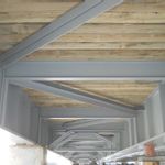
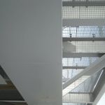
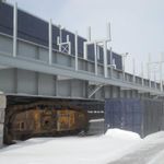
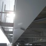
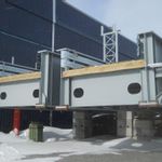
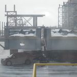
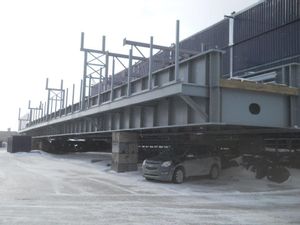
Detailed of the bridge design is given in another dpf file with 5 pages of drawings. The outer dimensions of the each of the 2 bridge sections are: 34m in Length, the main bridge itself is 2.5 m wide and 2.3 High according to the deisgn. But including the additional structures as shown in the photos, the overall dimension looks like about 5 m wide and 6 m high. It is suggested to take exact dimension measurements of these structures for road transportation.
The weight of these 2 structures: one is 167.8 MT and another is 169.6 MT.